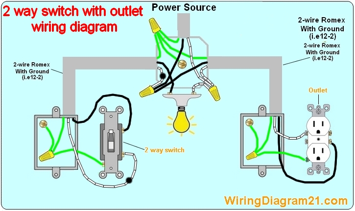
3 Way Switch Wiring Diagram Power At Switch

The white wire becomes the energized switch leg, as indicated by using black or red electrical tape.
3 way switch wiring diagram power at switch. Assortment of wiring diagram 3 way switch ceiling fan and light. This method is commonly used by professional electricians. The ground wire is pigtailed with a wire connector at the switch boxes and the ceiling box.
This might seem intimidating, but it does not have to be. The most important rationale is that there are several ways that a three way switch can be wired. In other words, a 3 way switch is made up of one light that’s controlled by two separate switches.
You must completely forget about the notion of a switch being a simple open/closed circuit and look at the diagram of the circuitry of this modern alternative. 3 way switch wiring diagram depicting all wires in the ceiling junction box. The goal is to place two switches at separate locations which control the exact same device.
3 way switch wiring with light first. 3 way switch wiring diagram. A dead end 3 way switch wiring method.
It reveals the elements of the circuit as streamlined shapes, and the power and also signal links in between the gadgets. Here are a few that may be of interest. The answer to how it works, is to have an …
A wiring diagram is a streamlined traditional photographic depiction of an electrical circuit. Regardless of what 3 way switch wiring diagram youre following youll need to use a 3 wire cable to connect the two 3 way light switches. Take a closer look at a 3 way switch wiring diagram.


